

Configuring dial peers is the key to implementing dial plans and providing voice services over an IP
packet network. Dial peers are used to identify call source and destination endpoints and to define the
characteristics applied to each call leg in the call connection.
Call Legs
A traditional voice call over the public switched telephone network (PSTN) uses a dedicated 64K circuit
end to end. In contrast, a voice call over the packet network is made up of discrete segments or call legs.
A call leg is a logical connection between two routers or between a router and a telephony device. A
voice call comprises four call legs, two from the perspective of the originating router and two from the
perspective of the terminating router, as shown in Figure 1.
Figure 1 Dial Peer Call Legs
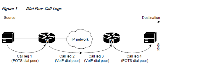
A dial peer is associated with each call leg. Attributes that are defined in a dial peer and applied to the
call leg include the codec, quality of service (QoS), voice activity detection (VAD), and fax rate. To
complete a voice call, you must configure a dial peer for each of the four call legs in the call connection.
Depending on the call leg, a call is routed using one of the two types of dial peers:
- Plain old telephone system (POTS)—Dial peer that defines the characteristics of a traditional
telephony network connection. POTS dial peers map a dialed string to a specific voice port on the
local router, normally the voice port connecting the router to the local PSTN, PBX, or telephone. - Voice-network—Dial peer that defines the characteristics of a packet network connection.
Voice-network dial peers map a dialed string to a remote network device, such as the destination
router that is connected to the remote telephony device.
Both POTS and voice-network dial peers are needed to establish voice connections over a packet
network.
When a voice call comes into the router, the router must match dial peers to route the call. For inbound
calls from a POTS interface that are being sent over the packet network, the router matches a POTS dial
peer for the inbound call leg and a voice-network dial peer for the outbound call leg. For calls coming
into the router from the packet network, the router matches an outbound POTS dial peer to terminate the
call and an inbound voice-network dial peer for features such as codec, VAD, and QoS.
Figure 2 shows the call legs and associated dial peers necessary to complete a voice call.

The following configurations show an example of a call being made from 4085554000 to 3105551000.
Figure 3 shows the inbound POTS dial peer and the outbound voice over IP (VoIP) dial peer that are
configured on the originating router. The POTS dial peer establishes the source of the call (via the calling
number or voice port), and the voice-network dial peer establishes the destination by associating the
dialed number with the network address of the remote router.
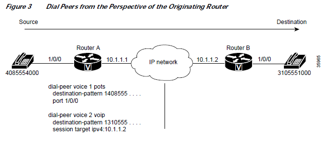
In this example, the dial string 14085554000 maps to telephone number 555-4000, with the digit 1 plus
the area code 408 preceding the number. When you configure the destination pattern, set the string to
match the local dialing conventions.
Figure 4 shows the inbound VoIP dial peer and outbound POTS dial peer that are configured on the
terminating router to complete the call. Dial peers are of local significance only.
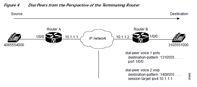
In the previous configuration examples, the last four digits in the VoIP dial peer’s destination pattern
were replaced with wildcards. Which means that from Router A, calling any telephone number that
begins with the digits “1310555” will result in a connection to Router B. This behavior implies that
Router B services all numbers beginning with those digits. From Router B, calling any telephone number
that begins with the digits “1408555” will result in a connection to Router A. This behavior implies that
Router A services all numbers beginning with those digits.
This type of configuration is similar to the configuration used for hairpinning, which occurs when a voice
call destined for the packet network is instead routed back over the PSTN because the packet network is
unavailable.
POTS Dial Peers
POTS dial peers retain the characteristics of a traditional telephony network connection. POTS dial peers
map a dialed string to a specific voice port on the local router, normally the voice port connecting the
router to the local PSTN, PBX, or telephone.
Voice-Network Dial Peers
Voice-network dial peers are components on an IP network to which a voice gateway router points via
the component’s IP address specified in the session-target command for a particular matching dial peer.
The four types of voice-network dial peers (VoIP, voice over ATM (VoATM), voice over Frame Relay
(VoFR), and multimedia mail over IP (MMoIP)) are determined according to the given packet network
technology and are described as follows:
- VoIP—Points to the IP address of the destination router that terminates the call.
- VoFR—Points to the data-link connection identifier (DLCI) of the interface from which the call exits
the router. - VoATM—Points to the ATM virtual circuit for the interface from which the call exits the router.
- MMoIP—Points to the e-mail address of the simple mail transfer protocol (SMTP) server. This type
of dial peer is used only for fax traffic
Data Dial Peers
Before Cisco IOS Release 12.2(11)T, a Cisco voice gateway would try to match a voice dial peer before
matching and processing a modem call. If a voice dial peer was matched, the call was processed as voice.
If there was no voice dial peer match, only then was a call considered to be a modem call. Voice calls
always received preference over modem calls. Also, there was no way to assign a subset of addresses in
the numbering plan for data calls.
In Cisco IOS Release 12.2(11)T, an interim solution in the form of application called “data_dialpeer”
was introduced to enable gateways to identify dial peers. The application enabled the handling of certain
matched calls as modem calls. Refer to the Fine-Grain Address Segmentation in Dial Peers feature
documentation in Cisco IOS Release 12.2(11)T for more information.
In Cisco IOS Release 12.2(13)T, formal support for data dial peers was released in the form of the
Dial-Peer Support for Data Calls feature, which enables the configuration and order assignment of dial
peers so that the gateway can identify incoming calls as voice or data (modem). You can use the
dial-peer data and dial-peer search commands to perform this configuration.
Creating a Dial Peer Configuration Table
Before you can configure dial peers, you must obtain specific information about your network. One way
to identify this information is to create a dial peer configuration table. This table should contain all the
telephone numbers and access codes for each router that is carrying telephone traffic in the network.
Because most installations require integrating equipment into an existing voice network, the telephone
dial plans are usually preset.
Figure 6 shows an example of a network in which Router A, with an IP address of 10.1.1.1, connects a
small sales branch office to the main office through Router B, with an IP address of 10.1.1.2.
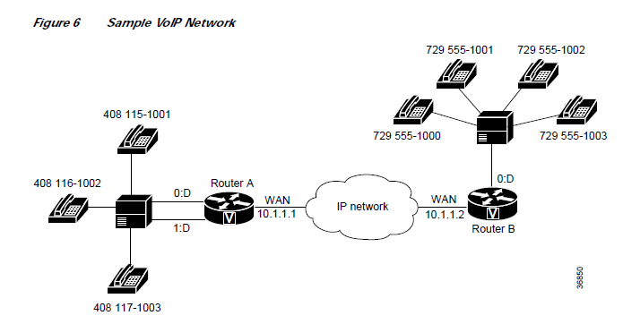
primary gateway to the main office; as such, it needs to be connected to the company’s PBX. Four
devices need dial peers, all of which are connected to the PBX, configured for them in the main office.
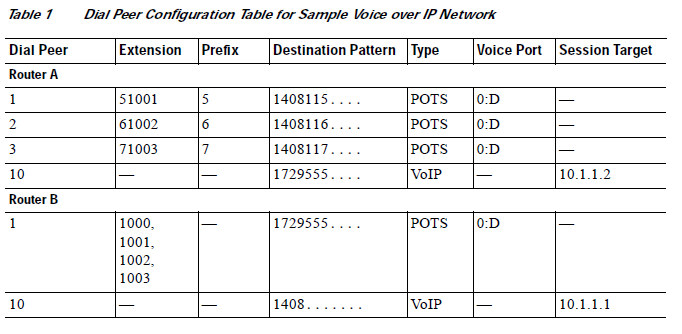
Table 1 shows the peer configuration table for the example in Figure 6.
Codecs
The term codec stands for coder-decoder. A codec is a particular method of transforming analog voice
into a digital bit stream (and vice versa) and also refers to the type of compression used. Several different
codecs have been developed to perform these functions, and each one is known by the number of the
International Telecommunication Union Telecommunication Standardization Sector (ITU-T) standard in
which it is defined. For example, two common codecs are the G.711 and the G.729 codecs.
Codecs use different algorithms to encode analog voice into digital bit streams and have different bit
rates, frame sizes, and coding delays associated with them. Codecs also differ in the amount of perceived
voice quality they achieve. Specialized hardware and software in the digital signal processors (DSPs)
perform codec transformation and compression functions, and different DSPs may offer different
selections of codecs.
Select the same type of codec at both ends of the call. For instance, if a call was coded with a G.729
codec, it must be decoded with a G.729 codec. Codec choice is configured on dial peers.
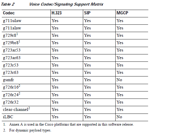
Table 2 lists the H.323, SIP, and MGCP codecs that are supported for voice.
For more information, refer to the “Configuring Dial Plans, Dial Peers, and Digit Manipulation” chapter
and the “Configuring Voice Ports” chapter in the Cisco IOS Voice, Video, and Fax Configuration Guide,
Release 12.2.
Clear Channel (G.Clear) Codec
G.Clear guarantees bit integrity when transferring a DS-0 through a gateway server, supports the
transporting of nonvoice circuit data sessions through a Voice over IP (VoIP) network, and enables the
VoIP networks to transport ISDN and switched 56 circuit-switched data calls. With the availability of
G.Clear, ISDN data calls that do not require bonding can be supported.
In a transit application, because it is possible to have a mix of voice and data calls, not supporting
G.Clear limits the solution to voice-only calls. The end-user application is in charge of handling packet
loss and error recovery. This packet loss management precludes the use of clear channel with some
applications unless the IP network is carefully engineered.
In an MGCP environment, the voice gateway backhauls the public switched telephony network (PSTN)
signaling channel to the call agent. The call agent examines the bearer capability and determines when
a G.Clear call should be established.
GSM Full Rate Codec
The GSMFR codec was introduced in 1987. The GSMFR speech coder has a frame size of 20 ms and
operates at a bit rate of 13 kbps. GSMFR is an RPE-LTP (Regular Pulse Excited – Linear Predictive)
coder.
In order to write VoiceXML scripts that can function as the user interface for a simple voice-mail system,
the network must support GSMFR codecs. The network messaging must be capable of recording a voice
message and depositing the message to an external server for later retrieval.
This codec supports the Cisco infrastructure and application partner components required for service
providers to deploy unified messaging applications.
Adaptive Differential PCM Voice Codec—G.726
Adaptive differential pulse code modulation (ADPCM) voice codec operates at bit rates of 16, 24, and
32 kbps. ADPCM provides the following functionality:
- Voice mail recording and playback, which is a requirement for Internet voice mail.
- Voice transport for cellular, wireless, and cable markets.
- High voice quality voice transport at 32 kbps.
iLBC Codec
The internet Low Bitrate Codec (iLBC) Has the following benefits:
- Is designed specifically for packet-based communication.
- Is royalty free.
- Provides high-voice quality, even in conditions with high-packet loss.
- Has a sampling rate of 8 kHz, for narrow band speech.
- Supports two fixed bit-rate frame lengths:
– Bit-rate of 13.3 kbps with an encoding frame length of 30 ms
– Bit-rate of 15.2 kbps with an encoding frame length of 20 ms - Is designed to be robust, even with packet loss. iLBC treats each packet independently and recovers
from packet loss on the packet immediately following the lost one. By utilizing the entire available
frequency band, this codec provides a high voice quality.
Platforms that iLBC Supports
iLBC is supported on Cisco AS5350XM and Cisco AS5400XM Universal Gateways with Voice Feature
Cards (VFCs) and IP-to-IP gateways with no transcoding and conferencing.
Using iLBC with SIP
- For iLBC codecs using SIP, use RFC3952 as a reference for implementation.
- Mid-call codec parameter changes using SIP are supported. For example, iLBC ‘mode’ and ‘ptime’
changes are supported using SIP during the call.
Using iLBC with H.323 - For iLBC codecs using H.323, a new proposal is written and submitted for approval to ITU. The new
proposal is added as ‘Annex S’ in H245, Version 12 which is used as reference for implementation.
See H245, version 12 document at http://www.packetizer.com/voip/h245/Version12/h245_ww9.zip - Mid-call codec parameter changes using H.323 are not supported.
Source Data: Cisco
The blog post titled “Dial Peer Configuration for Cisco Voice Gateway Routers” will be updated over time. You can stay tuned to receive the latest updates. Rıza Demir
